6.1 M&C Concept
The following paragraphs give a short introduction to the M&C software's architecture and explains some basic concepts of it. Here a digest in advance:
- The M&C software is built in a client - server architecture. The server dealing with the direct equipment control is a stand alone program running on that machine providing the hardware interfaces which control the equipment. Apart from this, the user interface is another program talking to the server by messages over an TCP/IP channel. A user interface program (client) may run on the M&C server itself or on any other machine having a network connection to the M&C server. There may be multiple clients connected to the same server at a time.
- As mentioned above, messages are used for the communication between the client and the server. Moreover, most of the internal communication between the server's components are done by messages, too. Messages report parameter settings or status information when sent to a client and the transport commands the operator enters at the user interface to the server. Chapter Parameter Messages explains this messaging mechanism more detailed.
- Within wide parts of the software, equipment settings are treated as abstract values. The M&C server uses pluggable modules called 'device drivers' to translate these values to commands the physical device understands. Device drivers are user configurable and user extensible, making the software highly adaptable. Chapter Device Drivers explains this device driver concept
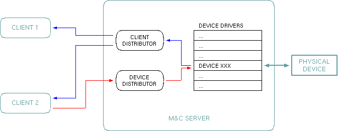
To deepen the explanations given above, this diagram shows a simple configuration with two clients (user interfaces) connected to a M&C server. With this example the flow of information shall be explained.
The first situation which shall be shown, is the polling of status information from the controlled device. The M&C software (more precisely: the device driver) polls all status information and all equipment settings on a regular basis. Control parameters like a frequency or data rate setting are polled less frequently, as they are not expected to change by themselves. At this point we will look to a frequently polled parameter like a lock alarm flag. The device driver polls this flag once a second. With each cycle the following actions are performed:
- The device driver sends a command string to the device, reads the response and decodes the 'lock alarm: yes/no' information from the device's reply.
- The device driver codes this information to a parameter message and forwards the message to the 'message distributor'.
- The message distributor looks in it's message memory for the previous value of this message. If there is a previous message and it contains the same state of this lock alarm, nothing happens. The distributor suppresses multiple messages with the same contents. If however the value has changed, the distributor remembers the new value and sends a copy of this message to every client which is interested in this parameter. In this case both clients will receive a message with the new lock alarm state.
Changing an equipment setting on an operator's request happens in a similar way. After the operator entered the new value at the user interface, the following steps are made by the software:
- The client software codes the value entered by the operator to a message. It sends this message to the M&C server.
- At the server, the 'device distributor' receives this message and routes is to the device driver of interest.
- The device driver receives the message and notes it down.
- Synchronized with it's polling activities, the driver picks up the changed value and translates it to a command string understood by the physical device. It sends this command string and processes the device's acknowledgment.
- Now the device driver triggers an extra polling cycle for the parameter it just has written. This way the parameter is read back and distributed in the same manner described above for the lock alarm fault flag.