CON1 LAN Connector
CON1 is the Ethernet 10Base-T / RJ45 connector. Use a standard network cable to connect the ACU to an Ethernet hub. If you want to connect your computer and the ACU directly without using a hub, you need a crossover cable for this with swapped RX/TX lines.
| pin | signal | description | type |
|---|---|---|---|
| 1 | TX+ | default Ethernet cabling (10Base-T) | OUT |
| 2 | TX- | OUT | |
| 3 | RX+ | IN | |
| 4 | |||
| 5 | |||
| 6 | RX- | IN | |
| 7 | |||
| 8 |
CON2 Spare Inputs
CON2 provides four opto-isolated spare inputs for the ACU. These inputs are reserved for customized versions of the ACU software, they normally are not used. There is no cabling required.
| pin | signal | description | type |
|---|---|---|---|
| 1 | AUX1 IN A | optional linear/circular switch position indication (linear pos.) | IN+ |
| 2 | AUX1 IN K | optional linear/circular switch position indication (linear pos.) | IN- |
| 3 | AUX2 IN A | optional linear/circular switch position indication (circular pos.) | IN+ |
| 4 | AUX2 IN K | optional linear/circular switch position indication (circular pos.) | IN- |
| 5 | AUX3 IN A | IN+ | |
| 6 | AUX3 IN K | IN- | |
| 7 | AUX4 IN A | IN+ | |
| 8 | AUX4 IN K | IN- |
If the ACU is configured to control a linear / circular switch, the AUX1 / AUX2 inputs are reserved for this function and may not be used as general purpose signals.
CON3 24V-EXT Distribution
CON3 provides eight clamps to the 24V-EXT rail. It has been included to simplify the external cabling.
| pin | signal | description | type |
|---|---|---|---|
| 1 | 24V_EXT | ||
| 2 | 24V_EXT | ||
| 3 | 24V_EXT | ||
| 4 | 24V_EXT | ||
| 5 | 24V_EXT | ||
| 6 | 24V_EXT | ||
| 7 | 24V_EXT | ||
| 8 | 24V_EXT |
CON4 Spare Outputs 5..8
CON4 provides four opto-isolated spare outputs for the ACU. These inputs are reserved for customized versions of the ACU software, they normally are not used. There is no cabling required.
| pin | signal | description | type |
|---|---|---|---|
| 1 | AUX 5 OUT C | OUT+ | |
| 2 | AUX 5 OUT E | OUT- | |
| 3 | AUX 6 OUT C | OUT+ | |
| 4 | AUX 6 OUT E | OUT- | |
| 5 | AUX 7 OUT C | OUT+ | |
| 6 | AUX 7 OUT E | OUT- | |
| 7 | AUX 8 OUT C | optional heartbeat signal | OUT+ |
| 8 | AUX 8 OUT E | optional heartbeat signal | OUT- |
The AUX 8 output may be configured to act as a heartbeat output. If enabled, the output switches every 1000 ms between on/off. If using this signal for an external watchdog circuit, be aware the in adaptive tracking mode delays of some seconds are possible while the acu calculates the orbital model.
CON5 Spare Outputs 1..4
CON5 provides another four opto-isolated spare outputs for the ACU. These inputs are reserved for customized versions of the ACU software, they normally are not used. There is no cabling required.
| pin | signal | description | type |
|---|---|---|---|
| 1 | AUX 1 OUT C | optional linear/circular switch drive output (linear pos.) | OUT+ |
| 2 | AUX 1 OUT E | optional linear/circular switch drive output (linear pos.) | OUT- |
| 3 | AUX 2 OUT C | optional linear/circular switch drive output (circular pos.) | OUT+ |
| 4 | AUX 2 OUT E | optional linear/circular switch drive output (circular pos.) | OUT- |
| 5 | AUX 3 OUT C | OUT+ | |
| 6 | AUX 3 OUT E | OUT- | |
| 7 | AUX 4 OUT C | OUT+ | |
| 8 | AUX 4 OUT E | OUT- |
If the ACU is configured to control a linear / circular switch, the AUX1 / AUX2 outputs are reserved for this function and may not be used as general purpose signals.
CON6 Beacon Receiver
The ACU preferably is used together with the sat-nms LBRX beacon receiver. With the sat-nms LBRX the ACU talks though TCP/IP, no additional cabling is required in this case. At CON6 the ACU provides an analog interface to third party beacon receivers.
| pin | signal | description | type |
|---|---|---|---|
| 1 | Beacon Level | beacon level signal 0..10V | IN |
| 2 | GND | ||
| 3 | PRESET 1 C | beacon receiver preset activation | OUT+ |
| 4 | PRESET 1 E | OUT- | |
| 5 | PRESET 2 C | beacon receiver preset activation | OUT+ |
| 6 | PRESET 2 E | OUT- | |
| 7 | PRESET 3 C | beacon receiver preset activation | OUT+ |
| 8 | PRESET 3 E | OUT- | |
| 9 | PRESET 4 C | beacon receiver preset activation | OUT+ |
| 10 | PRESET 4 E | OUT- |
CON7 Inclinometer
The ACU provides two ADC inputs to read the angle information from ratiometric inclinometers like the Schaevitz AccuStar. The standard ACU software reads this information and displays it at the 'Test' page of the software, but it does not include the nick/roll angles into the displayed antenna pointing.
| pin | signal | description | type |
|---|---|---|---|
| 1 | +9V | roll reference output (9VDC) | OUT |
| 2 | VRAT X | roll measurement input | IN |
| 3 | GND | roll ground | |
| 4 | +9V | nick reference output (9VDC) | OUT |
| 5 | VRAT Y | nick measurement input | IN |
| 6 | GND | nick ground |
CON8 Serial Interfaces
The ACU owns two serial interfaces. The first is reserved to poll a GPS receiver in order to get the antenna geodetic location automatically. Any NMEA standard GPS receiver providing a RS232 interface may be connected here.
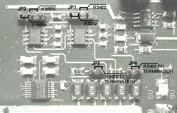
The second interface is used to control the ACU from remote where the TCP/IP remote control is not usable. This interface may be configured to work as a RS232 or RS422 interface by jumpers inside the ACU.
| pin | signal | description | type |
|---|---|---|---|
| 1 | RS232 0 TX | RS232 for GPS receiver | OUT |
| 2 | RS232 0 RX | IN | |
| 3 | GND | ||
| 4 | RS232 1 TX | RS232 for remote control | OUT |
| 5 | RS232 1 RX | IN | |
| 6 | GND | ||
| 7 | RS422 TX+ | RS422 for remote control | OUT+ |
| 8 | RS422 TX- | OUT- | |
| 9 | RS422 RX+ | IN+ | |
| 10 | RS422 RX- | IN- |
The ACU is factory preset to use the RS422 interface in 4-wire configuration. To change the interface configuration, set the jumpers on the ACU main board above CON8 according to the illustration below
CON9 Power Supply
At CON9 the power supply for the ACU itself (pins 1, 2) and for the external switches must be connected. Also see chapter 4.2.3 Power Supply Cabling for the concept of separate intern / extern power supplies the ACU uses.
| pin | signal | description | type |
|---|---|---|---|
| 1 | +24V ACU | power supply for the ACU and the | |
| 2 | GND ACU | positional encoders | |
| 3 | +24V EXT | power supply for motor drivers and | |
| 4 | GND EXT | external switches |
CON10 Azimuth Motor Driver
All signals for motor control are provided as free floating opto coupler inputs / outputs. This gives a maximum of flexibility to adapt the cabling to the motor driver units. They probably will combine one end of the control inputs to a common potential. The ACU is capable to control motor drivers with different polarity concepts.
 --- Example
for wiring the motor drive signals
--- Example
for wiring the motor drive signals --- Example for
wiring the motor status signals
--- Example for
wiring the motor status signalsThe ACU knows two different configuration modes to control a motor driver. They are called 'DIR-START' and 'DUAL-START'. In 'DIR-START' mode, the 'FWD' signal switches the motor on/off, the 'REV' signal controls the motor direction. This is the configuration many frequency inverters use. In 'DUAL-START' mode, the 'FWD' signal switches the motor on in forward direction, 'REV' activates the motor in reverse direction. This configuration mode is convenient to control a motor with relays.
The movement direction for the azimuth drive must be cabled as follows: FWD moves the antenna to the west (to the right on the northern hemisphere). The evaluation routines in the software which compute the antenna pointing for a given satellite location require the movement direction in this way.
The AZ RESERV reflects the "motor stopped" state of the axis. ON signals the OK state, the signal turns off in case of a motor fault, timeout, or if the emergency stop signal is received. Depending on the reason of the motor stop a motor reset command may be neccessary to release the axis from this state.
| pin | signal | DUAL-START | DIR-START | type |
|---|---|---|---|---|
| 1 | AZ FWD E | ON = motor on / right | ON = motor on | OUT- |
| 2 | AZ FWD C | OFF = motor off | OUT+ | |
| 3 | AZ REV E | ON = motor on / left | ON = direction left | OUT- |
| 4 | AZ REV C | OFF = direction right | OUT+ | |
| 5 | AZ SPD1 E | ON = slow | ON = slow | OUT- |
| 6 | AZ SPD1 C | OUT+ | ||
| 7 | AZ SPD2 E | ON = fast | ON = fast | OUT- |
| 8 | AZ SPD2 C | OUT+ | ||
| 9 | AZ RES E | reset driver | reset driver | OUT- |
| 10 | AZ RES C | OUT+ | ||
| 11 | AZ RESERV E | axis stopped | axis stopped | OUT- |
| 12 | AZ RESERV C | OUT+ | ||
| 13 | AZ FAULT K | driver fault | driver fault | IN- |
| 14 | AZ FAULT A | IN+ |
CON11 24V-EXT Distribution
CON11 provides four clamps to the 24V-EXT rail. It has been included to simplify the external cabling.
| pin | signal | description | type |
|---|---|---|---|
| 1 | +24V EXT | ||
| 2 | +24V EXT | ||
| 3 | +24V EXT | ||
| 4 | +24V EXT |
CON12 GND-EXT Distribution
CON12 provides four clamps to the GND-EXT rail. It has been included to simplify the external cabling.
| pin | signal | description | type |
|---|---|---|---|
| 1 | GND EXT | ||
| 2 | GND EXT | ||
| 3 | GND EXT | ||
| 4 | GND EXT |
CON13 Elevation Motor Driver
All signals for motor control are provided as free floating opto coupler inputs / outputs. This gives a maximum of flexibility to adapt the cabling to the motor driver units. They probably will combine one end of the control inputs to a common potential. The ACU is capable to control motor drivers with different polarity concepts.
--- Example
for wiring the motor drive signals --- Example for
wiring the motor status signalsThe ACU knows two different configuration modes to control a motor driver. They are called 'DIR-START' and 'DUAL-START'. In 'DIR-START' mode, the 'FWD' signal switches the motor on/off, the 'REV' signal controls the motor direction. This is the configuration many frequency inverters use. In 'DUAL-START' mode, the 'FWD' signal switches the motor on in forward direction, 'REV' activates the motor in reverse direction. This configuration mode is convenient to control a motor with relays.
The movement direction for the azimuth drive must be cabled as follows: FWD moves the antenna to the west to the right on the northern hemisphere. The evaluation routines in the software which compute the antenna pointing for a given satellite location require the movement direction in this way.
The EL RESERV reflects the "motor stopped" state of the axis. ON signals the OK state, the signal turns off in case of a motor fault, timeout, or if the emergency stop signal is received. Depending on the reason of the motor stop a motor reset command may be neccessary to release the axis from this state.
| pin | signal | DUAL-START | DIR-START | type |
|---|---|---|---|---|
| 1 | EL FWD E | ON = motor on / right | ON = motor on | OUT- |
| 2 | EL FWD C | OFF = motor off | OUT+ | |
| 3 | EL REV E | ON = motor on / left | ON = direction left | OUT- |
| 4 | EL REV C | OFF = direction right | OUT+ | |
| 5 | EL SPD1 E | ON = slow | ON = slow | OUT- |
| 6 | EL SPD1 C | OUT+ | ||
| 7 | EL SPD2 E | ON = fast | ON = fast | OUT- |
| 8 | EL SPD2 C | OUT+ | ||
| 9 | EL RES E | reset driver | reset driver | OUT- |
| 10 | EL RES C | OUT+ | ||
| 11 | EL RESERV E | axis stopped | axis stopped | OUT- |
| 12 | EL RESERV C | OUT+ | ||
| 13 | EL FAULT K | driver fault | driver fault | IN- |
| 14 | EL FAULT A | IN+ |
CON14 GND-EXT Distribution
CON12 provides eight clamps to the GND-EXT rail. It has been included to simplify the external cabling.
| pin | signal | description | type |
|---|---|---|---|
| 1 | GND EXT | ||
| 2 | GND EXT | ||
| 3 | GND EXT | ||
| 4 | GND EXT | ||
| 5 | GND EXT | ||
| 6 | GND EXT | ||
| 7 | GND EXT | ||
| 8 | GND EXT |
CON15 Polarization Motor Driver
All signals for motor control are provided as free floating opto coupler inputs / outputs. This gives a maximum of flexibility to adapt the cabling to the motor driver units. They probably will combine one end of the control inputs to a common potential. The ACU is capable to control motor drivers with different polarity concepts.
--- Example
for wiring the motor drive signals --- Example for
wiring the motor status signalsThe ACU knows two different configuration modes to control a motor driver. They are called 'DIR-START' and 'DUAL-START'. In 'DIR-START' mode, the 'FWD' signal switches the motor on/off, the 'REV' signal controls the motor direction. This is the configuration many frequency inverters use. In 'DUAL-START' mode, the 'FWD' signal switches the motor on in forward direction, 'REV' activates the motor in reverse direction. This configuration mode is convenient to control a motor with relays.
The movement direction for the polarization drive must be cabled as follows: FWD moves the feed clockwise when looking 'through the antenna' to the satellite. This is valid for the northern hemisphere, when operated on the southern hemisphere, the motor must be cabled for the opposite direction. The evaluation routines in the software which compute the antenna pointing for a given satellite location require the movement direction in this way.
The PL RESERV reflects the "motor stopped" state of the axis. ON signals the OK state, the signal turns off in case of a motor fault, timeout, or if the emergency stop signal is received. Depending on the reason of the motor stop a motor reset command may be necessary to release the axis from this state.
| pin | signal | DUAL-START | DIR-START | type |
|---|---|---|---|---|
| 1 | PL FWD E | ON = motor on / right | ON = motor on | OUT- |
| 2 | PL FWD C | OFF = motor off | OUT+ | |
| 3 | PL REV E | ON = motor on / left | ON = direction left | OUT- |
| 4 | PL REV C | OFF = direction right | OUT+ | |
| 5 | PL SPD1 E | ON = slow | ON = slow | OUT- |
| 6 | PL SPD1 C | OUT+ | ||
| 7 | PL SPD2 E | ON = fast | ON = fast | OUT- |
| 8 | PL SPD2 C | OUT+ | ||
| 9 | PL RES E | reset driver | reset driver | OUT- |
| 10 | PL RES C | OUT+ | ||
| 11 | PL RESERV E | axis stopped | axis stopped | OUT- |
| 12 | PL RESERV C | OUT+ | ||
| 13 | PL FAULT K | driver fault | driver fault | IN- |
| 14 | PL FAULT A | IN+ |
CON16 Limit Switches
The limit switch inputs internally are connected to the external 24V / GND rails. The switches are connected directly to the input pairs without any external ground or supply cabling. The ACU treats a closed contact as OK, contacts have to be opened to indicate the 'limit reached' condition.
 ---
Example for wiring the limit switches
---
Example for wiring the limit switchesPlease note, that the left/right azimuth and polarization limit switches have to be swapped when the antenna is operated at the southern hemisphere.
| pin | signal | description | type |
|---|---|---|---|
| 1 | AZ High | azimuth right limit (view from behind antenna) | IN |
| 2 | GND EXT | IN | |
| 3 | AZ Low | azimuth left limit (view from behind antenna) | IN |
| 4 | GND EXT | IN | |
| 5 | El High | upper limit Elevation | IN |
| 6 | GND EXT | IN | |
| 7 | El Low | lower limit Elevation | IN |
| 8 | GND EXT | IN | |
| 9 | Pol High | polarization right limit (view from behind antenna) | IN |
| 10 | GND EXT | IN | |
| 11 | Pol Low | polarization left limit (view from behind antenna) | IN |
| 12 | GND EXT | IN |
CON17 Alarm Circuits
The alarm/stop switch inputs internally are connected to the external 24V / GND rails. The switches are connected directly to the input pairs without any external ground or supply cabling. The ACU treats a closed contact as OK, contacts have to be opened to activate the function noted in the table below.
The fault output are mechanical relays which connect '_C' (common) circuit to the '_NC' (normally closed) circuit while the ACU is powered and OK. In case of a fault or a lack of power supply the relays connect the '_NO' circuit to the '_C' circuit.
| pin | signal | description | type |
|---|---|---|---|
| 1 | EMER_STOP | emergency stop (OK if closed) | IN |
| 2 | GND_EXT | IN | |
| 3 | ANT_HUB_FAULT | alarm: hub fault (OK if closed) | IN |
| 4 | GND_EXT | IN | |
| 5 | SW_CAB_OPEN | alarm: cabinet open (OK if closed) | IN |
| 6 | GND_EXT | IN | |
| 7 | ACU_FLT_NC | acu alarm (connected to 9 if OK) | RELAY |
| 8 | ACU_FLT_NO | (connected to 9 if there is a FAULT) | RELAY |
| 9 | ACU_FLT_C | RELAY | |
| 10 | TRK_FLT_NC | tracking alarm (connected to 12 if OK) | RELAY |
| 11 | TRK_FLT_NO | (connected to 12 if there is a FAULT) | RELAY |
| 12 | TRK_FLT_C | RELAY |
CON18, CON19, CON20 Resolver Interface
Below the pinout of a resolver type interface board is shown. The ACU is available with resolver, SSI or analog position sensor interfaces. You have to select type of interface when you order the ACU.
| pin | signal | description | type |
|---|---|---|---|
| 1 | GND | ||
| 2 | SIN | resolver SIN | IN |
| 3 | GND | resolver SIN | IN |
| 4 | COS | resolver COS | IN |
| 5 | GND | resolver COS | IN |
| 6 | REF | drive signal to resolver | OUT |
| 7 | GND | drive signal to resolver | OUT |
| 8 | GND |
The ACU resolver interface is designed for resolvers with an impedance of 100 Ohms or more and transfer factor 0.5. The interface applies 4Veff / 2000Hz to the resolver drive coil. It expects 2Veff at the sine / cosine inputs at the maximum positions.
When connecting a resolver to the ACU, please consider the following:
CON18, CON19, CON20 SSI Positional Encoder Interface
Below the pinout of a SSI type positional encoder interface board is shown. The ACU is available with resolver, SSI or analog position sensor interfaces. You have to select type of interface when you order the ACU.
The SSI positional encoder may be powered from the ACU internal power supply. +5V and +24V clamps are provided at the connector. To avoid ground loops, the cable shield should be connected either to pin 1 at the ACU or to the ground at the encoder housing, never at both ends.
| pin | signal | description | type |
|---|---|---|---|
| 1 | GND | ||
| 2 | SSI-Data+ | SSI data | IN |
| 3 | SSI-Data- | SSI data | IN |
| 4 | SSI CLK+ | SSI clock | OUT |
| 5 | SSI CLK- | SSI clock | OUT |
| 6 | |||
| 7 | +5V | encoder power supply | |
| 8 | +24V | encoder power supply |
CON18, CON19, CON20 Analog Angle Sensor Interface
Below the pinout of an analog type positional sensor interface board is shown. The ACU is available with resolver, SSI or analog position sensor interfaces. You have to select type of interface when you order the ACU.
| pin | signal | description | type |
|---|---|---|---|
| 1 | AGND | analog ground | OUT |
| 2 | INPUT | A/D converter input | IN |
| 3 | REF | reference voltage | OUT |
| 4 | AGND | analog ground | OUT |
| 5 | +15V (opt) | optional DC out | OUT |
| 6 | -15V (opt) | optional DC out | OUT |
| 7 | +9V (opt) | optional DC out | OUT |
| 8 | GND | digital ground | OUT |