In standard configuration only digital inputs at CON 6, 7, 8 and 9 (digital input No. 1...16) are available. The other digital inputs are deactivated in standard delivery state. They can easily be enabled by entering the corresponding feature code. See chapter 2.4.1 Feature code activation for further information. Call SatService GmbH sales team for purchasing a feature code.
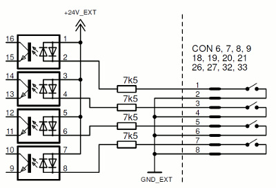
The digital input interfaces are used to monitor potential-free contacts. Indication current provided by sat-nms IO-FEP2 is approx 3mA. Never put external Voltage to these pins, sat-nms IO-FEP2 might be damaged in this case. all of these interfaces have the same connector layout: Pin1 and Pin2 is one input, Pin3 and Pin4 is the next one and so on. Fox exact pin layout, please refer to chapter 5 Connector Reference .
For each input there is one green LED available showing actual state. LED is ON, when corresponding input is CLOSED. If LED is OFF, corresponding input is OPEN.
The digital inputs at CON32 and CON33 are configured as all the other inputs by default. The nevertheless might be configured to detect a 24V-Signal. Have a look at chapter 2.4.4 Detect 24V DC signals with DIN41...48 to learn how to configure these digital inputs to be able to detect a 24V-Signal.