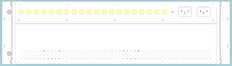
On the rear side the in-/ out RF-connectors are placed. Depending, which card is placed in the corresponding slot, the connector is an in- or an output.
If e.g. in slot 1 a LFTX card is placed, the connector I/O 1 is a RF-input. If there is placed a LFRX-card, I/O 1 is a RF-output.
In the standard configuration all RF-connectors are SMA/ 50Ohm female connectors. If you need other connectors e.g. BNC or F or an 75Ohm impedance, contact SatService, we are able to customize the sat-nms LFTXRX.
See chapter, (50/75Ohm converter) , (1:4 splitter) or (dual coupler) for some options.
On the front side of every LFTX or LFRX card you can find a SMA-connector female labelled with TPout -10dB . Here it is possible to measure the RF Signal connected to the corresponding I/O-connector with an attenuation of approx. 10dB. This difference may vary due to different configurations of the sat-nms LFTXRX frame. On the LFTX card the attenuator is additionally taken into account (see block diagram).