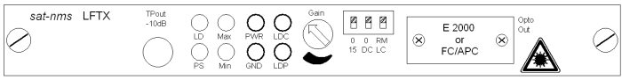
The following picture shows you the front view of a LFTX card.
Depending on the card configuration, the 'Opto Out' connector is an E2000 or a FC/APC connector. Connect here the optical fibre to transmit the optical signal.
The following indicator LED's are located on the cards front panel:
| Parameter | Description |
|---|---|
| LD | This (green) LED shows the state of the TX laser diode. The LED turns on, if the laser diode is working. |
| PS | The (green) PS-LED displays the power supply state of the card. The LED is on, if the power supply of the card is working. |
| Max | The (yellow) Max-LED turns on, if the RF input level is above the recommended level. RFmax Alarm level: typ. -10dBm (-11...-5dBm) |
| Min | The (yellow) Max-LED turns on, if the RF input level is below the recommended level. RFmin Alarm level: typ. -23dBm (-25...-20dBm) |
You have the possibility to change the following parameters:
| Parameter | Description |
|---|---|
| Gain | An integrated attenuator makes is possible to attenuate the RF-input-signal in 1dB-steps from 0 to 31dB. This switch has 16 steps. Use the 0..15 switch to select the attenuation range to 0-15dB or 16-31dB. |
| 0..15 | By setting this switch, you define the range of attenuation, that can be set by the gain switch. In the 0 position, it is possible to set the attenuator from 0-15dB, in the 15 position, the attenuation value can be set from 16-31dB. |
| 0..DC | If your card is equipped with this functionality, you can switch here the 15VDC on and off to supply a LNC connected to the RF in of this slot. In the 0 position of the switch, 15VDC is off, in the DC position, the 15VDC is on. |
| RM/LC | This DIP-switch defines, if the card is controlled remote RM or local LC . If the switch is in the LC position, it is not possible, to change the parameters of this card via remote Interface (IP, RS232, SNMP) or via the front panel keyboard of the LFTX/RX chassis. |
Additionally you can measure the following parameters:
| Parameter | Description |
|---|---|
| TPout -10dB | The testport gives you the opportunity to measure the RF-Level on the Front panel. The Signal, that you can measure here is about 10dB lower than the output signal on the back side of the LFTX/RX chassis. This difference may vary due to optional configurations integrated to the sat-nms LFTX/RX Frame (e.g. redundancy switching, 1:4 splitter, 50/75 converter) |
| PWR | Here you can measure the level of the RF power. The scaling is 50mV/dB |
| GND | Reference Ground for the PWR, LDC and LDP measurement. |
| LDC | Here you can measure the current consumption of the laser diode. 100mV relates to 10mA. |
| LDP | Here you can measure the optical power. 100mV relates to 100uW. |