2.4 Connecting the sat-nms LFTRX
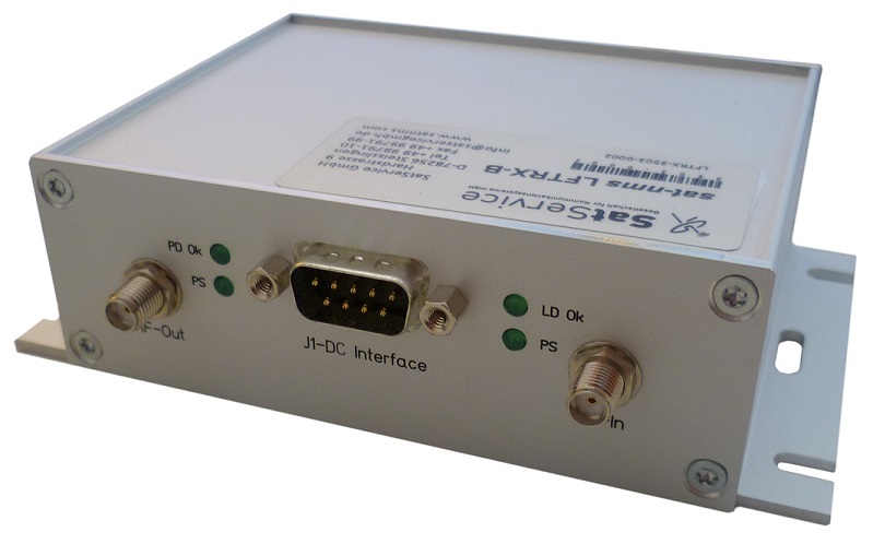
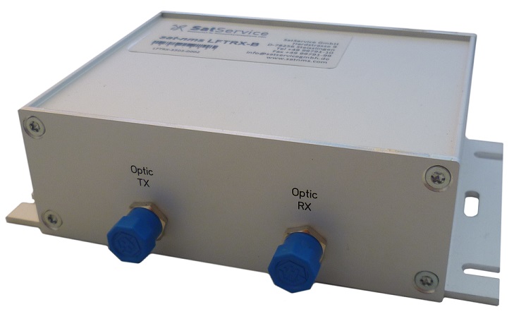
The connectors of the enclosure are placed on the front and on the rear side. The rear side contains the fibre optic connectors, the front side contains the the corresponding RF In/Out connectors and also the the DC-power and Data-connector.
When you connect the L-Band Optical Link chassis, please consider the following:
- J1 DC-Power Interface is a standard 9-pin SUB-D socket-connector. This connector contains the alarm contacts of the internal failure open collecttor transistor, the signal monitor and the DC-Power Supply Input. To meet mentioned EMC standards, use double shielded twisted pair CAT7 S/FTP Network cable, e.g. DRAKA UC900 SS27 Cat.7 PUR. Take care, that cable shielding is connected properly.
- RF-In/ Out RF-Interface The input and output RF-connectors are all SMA/50Ohm female. Use double shielded coaxial cables, e.g. RG223, only.
- Optic TX/ RX Optic-Interface The fibre optic connectors are FC/APC types. It is essentially to use single mode cables with 8° angled polish for proper function.