9.35 Agilent-Spectrum-Analyzer
This page describes the device driver and the device window for HP / Agilent ESA spectrum analyzers. Actually the driver supports Agilent ESA E44xx analyzers equipped with a serial (RS232) interface. It provides a remote control of the basic parameters of the device.
Device window pages
The following table shows which device window pages are available with this individual device type. Tool-bar functions not mentioned here are described at the general description of device windows .
 --- The spectrum view.
 --- The main parameter page displays/controls the spectrum main analyzer settings like center frequency, span, etc. You get this page in it's own window beside the spectrum view if you click to 'SET' at the upper left corner of the spectrum view window.
 --- This page gives you access to the first 16 instrument memories of the spectrum analyzer. Clicking to 'STO x' stores the actual instrument settings to this memory place in the device. Clicking to 'RCL x' recalls the selected memory.You may use the text field between the buttons to note a comment for this particular memory place. Unless the instrument settings which are stored in the device itself, the text is stored at the VLC/M&C system. Hence, if you replace the spectrum analyzer, the stored instrument settings are gone with the replaced device, the comments however are still present.Also this page is available as a separate window. click to 'PRE' at the upper left corner of the spectrum view to launch a 'preset' window without leaving the spectrum view.
 --- The faults page.
 --- The device info page.
 --- The maintenance page. The configuration parameters described below are set at this page.
Configuration parameters
At the maintenance page of the device window there are a couple of configuration parameters which must be set to make the software talk to the antenna controller.
- parameter --- description
- address --- The spectrum analyzer remote protocol does not use a device address. Leave this field empty.
- display --- This configuration parameter switches the local display of the spectrum analyzer on or off. Switching off the display improves the measurement speed of the analyzer in some situations.
- Serial --- The serial line parameters of interface used to drive the spectrum analyzer must be set to the same values set at the device itself (Accessible at the front panel using the 'System' menu). Regardless of the speed, RTS/CTS handshaking must be enabled and a full-wired RS232 cable must be used to the connect the spectrum analyzer to the M&C/VLC.The recommended line speed for the interface depends on the situation where the spectrum analyzer is used. Depending on the speed of the M&C/VLC system and the line speed used to drive the spectrum analyzer there results a maximum sweep rate the system can handle. This sweep rate must not exceed the capacity of the communication line to the NMS or the user interface. The recommended line speeds listed below restrict the sweep rates to values which avoid communication buffer overflows. | environment | line speed | max. sweep rate | | ---- | ---- | ---- | | VLC, connected to the NMS via modem dial up | 9600,E,8,1 | 0.3 / sec | | VLC, connected to the NMS via ISDN dial up or LAN | 19200,E,8,1 | 1 / sec | | M&C system, clients are connected via LAN or ISDN | 38400,E,8,1 | 2 / sec |
See also the note about sweep handling.
The spectrum view
The spectrum view shows the spectrum analyzer's output in a similar format as the local display would do. The display shows the measured spectrum (white) in front of a graticule and a summary of instrument settings.
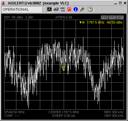
Clicking into the spectrum display activates the marker. You may drag the mouse with the button held down to see a reticule which follows the spectrum curve. This helps to place the marker manually to peaks. More about marker measurements you find at the next paragraph below.
At the upper left corner of the spectrum view you find three 'buttons' which activate additional function when you click to one of them.
- PRE --- Launches a separate window showing the instrument memory page.
- PRT --- Opens the printing dialog, lets you print out the actual spectrum display.
- SET --- Launches a separate window showing the instrument settings page.
Marker handling
The spectrum view supports two markers. The main marker is that one provided by the instrument itself. The spectrum view colors this marker yellow. You may set the marker manually by clicking with the left mouse button into the spectrum display. While you hold down the mouse button, a reticule is shown which helps you to place the marker precisely. The instrument settings page provides some common marker functions like 'peak search' or 'marker to center'. These function operate on this main marker.
Additionally the spectrum display provides a delta marker function. To use this function, first place the marker to the location you want to become the reference for the delta measurement. Then set the marker to a second location using the right mouse button. This stores the previous marker location as reference (now shown green) to the actual marker location. You may do several delta measurement with the same reference point placing the marker with the right mouse button. Also the peak search and next peak functions work as you might expect. As soon as you place a marker with the left mouse button, the reference point and the delta display gets deleted.
As the marker is based on the instrument's internal marker function, the response to your mouse clicks may be somewhat delayed, specially with a slow communication line. Using the single sweep mode when setting markers improves the performance significantly.
Sweep handling
Viewing the output of a spectrum analyzer at a remote place requires a quite large amount of data to be transferred. Depending on system limitations like the capacity of communication lines this restricts the display update rate to value much lower than the rates you can achieve locally at the instrument.
The spectrum analyzer device driver always operates the instrument in 'single sweep' mode. It manually (i.e. with a remote command) triggers a sweep, when the sweep has finished the trace data is read out and sent to the user interface. The continuous sweep mode selectable at the M&C user interface is implemented in the device driver by repeatedly performing the sequence described above.
Unlike the instrument's local display, the spectrum view shows complete sweeps only. With long sweep times you will find the display frozen until the sweep has completed an the trace data has been transferred to your user interface. With short sweep times, the maximum sweep rate will be limited by the maximum rate the M&C system is capable to handle and to transfer to the user interface rather than by the sweep time itself.
When you change instrument parameters at the M&C user interface, the device driver automatically triggers a new sweep if the driver is in single sweep mode. With a slow VLC and/or a slow communication line you will see a noticeable delay between the parameter change an the screen update.
Variables defined by this device driver
| info.driver |
TEXT |
R/O |
StringRange R/O |
| info.type |
TEXT |
R/O |
StringRange R/O |
| info.port |
TEXT |
R/O |
StringRange R/O |
| info.frame |
TEXT |
R/O |
StringRange R/O |
| info.manufacturer |
TEXT |
R/O |
StringRange R/O |
| info.model |
TEXT |
R/O |
StringRange R/O |
| info.serial |
TEXT |
R/O |
StringRange R/O |
| info.revision |
TEXT |
R/O |
StringRange R/O |
| info.screen |
TEXT |
R/O |
StringRange R/O |
| invalidate.mkr |
TEXT |
R/O |
StringRange R/O |
| invalidate.lev |
TEXT |
R/O |
StringRange R/O |
| invalidate.frq |
TEXT |
R/O |
StringRange R/O |
| invalidate.swp |
TEXT |
R/O |
StringRange R/O |
| invalidate.oth |
TEXT |
R/O |
StringRange R/O |
| invalidate.alw |
TEXT |
R/O |
StringRange R/O |
| internal.x |
FLOAT |
R/O |
DoubleRange R/O (0.000000 .. 0.000000) |
| internal.lofr |
FLOAT |
R/O |
DoubleRange R/O (0 .. 0) |
| config.display |
CHOICE |
SETUP |
EnumRange (OFF ON) |
| config.bandEdge |
FLOAT |
SAVE SETUP |
DoubleRange (0 .. 0) |
| config.loFreqLow |
FLOAT |
SAVE SETUP |
DoubleRange (0 .. 0) |
| config.loFreqHigh |
FLOAT |
SAVE SETUP |
DoubleRange (0 .. 0) |
| center |
FLOAT |
|
DoubleRange (0.000000 .. 0.000000) |
| span |
FLOAT |
|
DoubleRange (0.000000 .. 0.000000) |
| span.full |
TEXT |
|
StringRange |
| span.dn |
TEXT |
|
StringRange |
| span.up |
TEXT |
|
StringRange |
| reflev |
FLOAT |
|
DoubleRange (0.00 .. 0.00) |
| reflev.up |
TEXT |
|
StringRange |
| reflev.dn |
TEXT |
|
StringRange |
| scale |
FLOAT |
|
DoubleRange (0 .. 0) |
| atten |
FLOAT |
|
DoubleRange (0 .. 65) |
| atten.auto |
CHOICE |
|
EnumRange (AUTO FIX) |
| rbw |
FLOAT |
|
DoubleRange (0.000 .. 0.000) |
| rbw.up |
TEXT |
|
StringRange |
| rbw.dn |
TEXT |
|
StringRange |
| vbw |
FLOAT |
|
DoubleRange (0.000 .. 0.000) |
| vbw.up |
TEXT |
|
StringRange |
| vbw.dn |
TEXT |
|
StringRange |
| sweep |
FLOAT |
|
DoubleRange (0.004 .. 4000.000) |
| rbw.auto |
CHOICE |
|
EnumRange (AUTO FIX) |
| vbw.auto |
CHOICE |
|
EnumRange (AUTO FIX) |
| sweep.auto |
CHOICE |
|
EnumRange (AUTO FIX) |
| trigger |
CHOICE |
SAVE |
EnumRange (CONT SINGLE) |
| trace |
GENERIC |
R/O |
ObjectRange R/O generic object |
| sweeping |
TEXT |
R/O |
StringRange R/O |
| display |
CHOICE |
|
EnumRange (NORM MAX HOLD MIN HOLD) |
| marker.x |
FLOAT |
R/O |
DoubleRange R/O (0.000000 .. 0.000000) |
| marker.y |
FLOAT |
R/O |
DoubleRange R/O (0.00 .. 0.00) |
| marker.xpos |
INTEGER |
|
IntegerRange (0 .. 0) |
| marker.mode |
CHOICE |
|
EnumRange (OFF ON) |
| marker.peak |
TEXT |
|
StringRange |
| marker.nextPeak |
TEXT |
|
StringRange |
| marker.toCenter |
TEXT |
|
StringRange |
| marker.toReflev |
TEXT |
|
StringRange |
| reset |
TEXT |
|
StringRange |
| lowLevel.cmd |
TEXT |
|
StringRange |
| lowLevel.reply |
TEXT |
R/O |
StringRange R/O |
| store |
TEXT |
|
StringRange |
| recall |
TEXT |
|
StringRange |
| memname.0 |
TEXT |
SAVE |
StringRange |
| memname.1 |
TEXT |
SAVE |
StringRange |
| memname.2 |
TEXT |
SAVE |
StringRange |
| memname.3 |
TEXT |
SAVE |
StringRange |
| memname.4 |
TEXT |
SAVE |
StringRange |
| memname.5 |
TEXT |
SAVE |
StringRange |
| memname.6 |
TEXT |
SAVE |
StringRange |
| memname.7 |
TEXT |
SAVE |
StringRange |
| memname.8 |
TEXT |
SAVE |
StringRange |
| memname.9 |
TEXT |
SAVE |
StringRange |
| memname.10 |
TEXT |
SAVE |
StringRange |
| memname.11 |
TEXT |
SAVE |
StringRange |
| memname.12 |
TEXT |
SAVE |
StringRange |
| memname.13 |
TEXT |
SAVE |
StringRange |
| memname.14 |
TEXT |
SAVE |
StringRange |
| memname.15 |
TEXT |
SAVE |
StringRange |
| faults.99 |
ALARM |
R/O |
AlarmFlagRange R/O (Communication) |
| faults.commstat |
TEXT |
R/O |
StringRange R/O |