sat-nms ACUs with the tracking function installed give access to the tracking mode and the fine tune parameter which lets you adapt the tracking to the individual requirements of the antenna and the satellite you are tracking to. ACUs without tracking function show an empty page at this place.
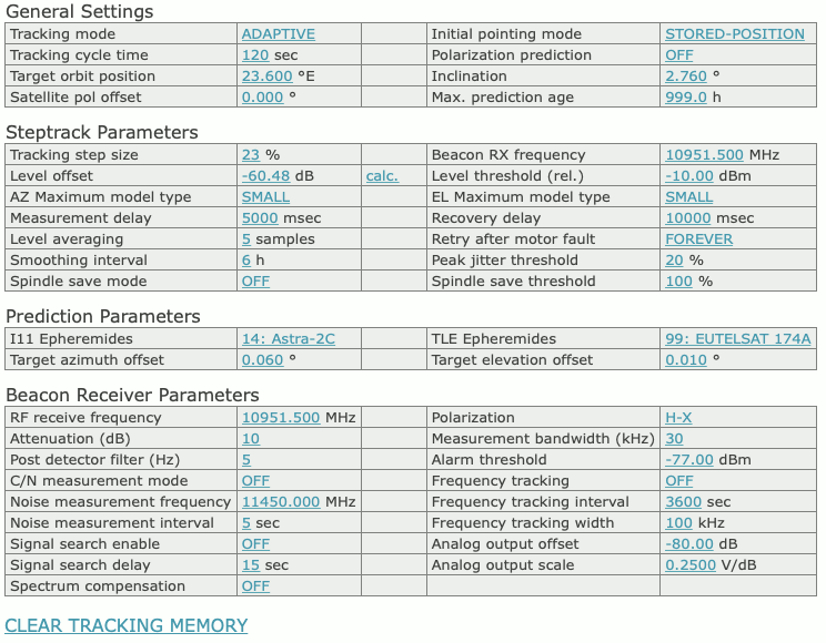
General Settings
Steptrack Parameters
Tracking step size — The tracking step size is a very important parameter for the performance of the tracking. It defines the size of every depointing step, the ACU makes in order to find out where the optimal antenna pointing is. Setting too high values will cause significant signal degradations during the step track cycle because the antenna moves a too large amount away from the satellite. Setting the value too small will let the beacon level jitter mask the level differences caused by the test steps, the antenna will not track the satellite properly.The step size is specified as a percentage of the antenna’s half 3dB beamwidth. The ACU calculates the beamwidth from the antenna diameter and the beacon frequency. Expressing the step size in this relative way keeps the value in the same range, regardless of the type of antenna. The recommended value for this parameter is 15-20%. You may want to start with 20% and try to reduce down to 15% if the signal degradation during tracking becomes too high.The tracking step size is a common parameter for both axes. If both axes behave differently, you can tweak the antenna diameter settings in the setup. Specifying a larger diameter makes the ACU using a smaller step size for this axis.If the tracking step seems to be completely out of range, you should check if the beacon frequency is set properly. The frequency must be the true receive frequency at the antenna, entered in MHz, not an L-band frequency or other IF.
Beacon frequency — This parameter tells the ACU the frequency of the beacon signal to be used for tracking. The ACU calculates the antenna beam width from this frequency and the antenna diameter configured at the setup page. The value has to be entered as true receive frequency, no L-band or other IF frequency. When used with a SatService beacon receiver, the ACU automatically reads the beacon frequency at the start of each tracking cycle from the receiver. Any value entered here will be overwritten in this case. The beacon frequency entered here never sets the frequency at the receiver, neither with a SatService receiver nor with a third party device!
Level offset — Principally there are two ways to display a beacon receive level: Either as an absolute level in dBm as reported by the receiver or as a relative level with ‘0dB’ signalling the nominal level at clear sky conditions. The latter gives an easy measure for any degradation of the receive level.The parameter ‘Level offset’ lets you calibrate the absolute reading of the beacon receiver to the relative level. You may either enter a value to shift the reading by this offset or you may click to the ‘calc.’ link beside this parameter to set the offset to the actual absolute level reading, making the actual level being 0dB relative.
Level threshold — If the relative beacon level falls below this threshold value, the ACU does not perform a step track cycle. If the level falls below the threshold during the steptrack cycle, the cycle gets aborted. If the ADAPTIVE tracking is enabled and there is enough data in the tracking memory, the ACU computes a mathematical model from the stored data and predicts the antenna pointing position from the extrapolation of the model. Analogously the antenna is moved to the actual TLE it I11 position in such a case if the ‘STEP-TLE’ or ‘STEP-I11’ mode is selected. If the tracking mode is set to ‘STEP’, the ACU leaves the antenna where it is if the beacon level drops below the limit.
Adjusting the threshold level that adaptive tracking is switched as expected must be done carefully and may require some iterations, specially if the beacon is received with a low C/N.
A good starting value for the threshold is 10 dB below the nominal receive level or 2 dB above the noise floor the beacon receiver sees with a depointed antenna, whatever value is higher. As mentioned above, the level threshold refers to the relative beacon level, not to the absolute level reading.
To turn off the monitoring of the beacon level (this in fact inhibits the adaptive tracking), simply set the threshold the a very low value (e.g. -99 dBm)
AZ Maximum model type / EL Maximum model type — These settings let you limit the adaptive model to a simpler one, the ACU would choose by itself. The maximum model type can be set individually for each axis. Normally you will set both axes to ‘LARGE’, which leaves the model selection fully to the ACU’s internal selection algorithms.In cases where the ACU seems to be too ‘optimistic’ about the quality of the step track results, the maximum model on one or both axes may be limited to a more simple and more noise-resistant model. Specially inclined orbit satellites which are located close to the longitude of the antenna’s geodetic location may require this limitation for the azimuth axis. With such a satellite, the elevation may move several degrees while the azimuth shows almost no motion.
Measurement delay — During a steptrack cycle, the ACU positions the antenna to a certain offset and then measures the level. Between the moment when the antenna reached commanded position and the beacon level measurement the ACU waits some time to let the beacon level settle. The optimal delay value depends on the beacon receiver’s averaging / post detector filter setting and is a quite critical for the steptrack performance.If the delay is too short, the beacon voltage does not reach its final value, the steptrack does not properly recognize if the signal goes better or worse after a test step. If the delay is too long, the impact of fluctuation to the measured level grows and may cover the small level difference caused by the test step. With the sat-nms LBRX beacon receiver, best results are achieved if the receiver is set to 0.5 Hz post detector filter bandwidth and a measurement delay of 1500 msec.
Recovery delay — After the ACU has done the tracking steps for the elevation axis, it waits some time before it starts tracking the azimuth axis. This is to let the beacon level settle after the final position has been found. A typical value for this parameter is 4000 msec.
Level averaging — When measuring the beacon level, the ACU takes a number of samples and averages them. The standard value of 5 samples normally should not be changed. Larger values will slow down the ACU execution cycle.
Retry after motor fault — When the ACU encounters a motor fault during steptrack, the tracking cycle gets aborted and the ACU shows a fault. This parameter tells the ACU how to proceed after this, with the next tracking cycle:
Smoothing interval — This parameter controls the smoothing function. Setting it to zero disables smoothing. Smoothing lets the ACU point the antenna to positions evaluated from a simple model calculated from the step track peaks of the recent few hours. A detailed description of this function you find at chapter ‘8.3.3 Smoothing’
Peak jitter threshold — If the jitter value of at least one axis exceeds this threshold, the ACU raises an ‘model fault’. If this happens three consecutive times, the ACU resets the models of both axes. Adaptive tracking will be possible not until 6 hours after this happens.During adaptive tracking, the ACU evaluates for each axis a figure called jitter. The jitter value describes standard deviation of the measured peak positions with respect to the positions calculated from the (currently selected) model. The figure is also expressed as a percentage of the antenna’s beamwidth, low values indicate, that the model ideally describes the antenna’s path. High values indicate that’s something wrong. The step track results may be to noisy at low amplitudes or the model does not fit at all. This may be the case if a satellite gets repositioned in the orbit.A typical threshold value is 20%, this will detect very early that a model does not fit to describe the satellite’s motion. If this value causes false alarms too often, you may want to raise the threshold to 50%. Setting it to 0 switches the threshold monitoring completely off.
Spindle save mode — If set to OFF, the ACU does a step track optimization with every tracking cycle. If set to a value 1 .. 12, the ACU will insert steps where it positions the antenna following the actual ADAPTIVE model. If e.g. the spindle save mode is set to 2, the ACU will do a step track optimization in the first cycle, in the second and third cycle it skips this and moves the antenna following the actual ADAPTIVE model. This reduces the number of antenna movements and spindle wear.
Spindle save threshold — Defines the model quality (jitter value) neccessary to replace step track optimization steps in spindle save mode. If the jitter value of one axis exceeds this value, the ACU does step track optimization steps everycle even if spindle save mode ist active.
Model hysteresis — If set to a non-zero value, antenna movements below this threshold are suppressed whenever the antenna is controlled by an adaptive model or by ephemeris data. The value is expressed as a percentage of the half 3dB beamwidth of the antenna. You may use this parameter to reduce the number of antenna movements in these modes.
Apply model before track — If set to ON the ACU moves the antenna to a position calculated by the actual adaptive model before it starts a steptrack optimization sequence. With inclined orbit satellites this helps to follow the satellite with minimized level degradation.
Prediction Parameters
Beacon Receiver Parameters
If the ACU is configured to work together with a sat-nms beacon receiver, the receiver’s settings may be remote controlled from this section of the target parameters. The beacon receiver settings are stored when a target memory is saved and and set at the beacon receiver when a target memory is recalled. Beacon receiver parameters are not available if the ACU works with a 3rd party beacon receive
CLEAR TRACKING MEMORY
Clicking to this mark clears the tracking memory. You should do this when you start to track a new satellite. Clearing the tracking memory about half an hour after tracking started significantly improves the quality of the first adaptive tracking model which will be evaluated after 6 hours of tracking. This is because the model does not get disturbed by the first search steps the antenna does until the optimal pointing to the satellite is found.
Please refer to chapter 8.3 Steptrack , 8.4 Adaptive Tracking and 8.5 Program Tracking for more detailed informations about the tracking algorithms.