
Attention: Optical Radiation!
If connected to a power supply, the LFTXRX provides invisible laser radiation. The source is class 3R Laser diode as defined in DIN EN 60825-1:2001-11 with P0=2mW, Lambda=1310nm. Never look into fibre-optical components like connectors or fibres. Use an infrared viewer, optical power meter or fluorescent screen for optical output verification.
It is possible to realize up to 20 optical links with one sat-nms LFTXRX chassis. Alternativ it is possible to plug in a sat-nms LFSW card, which allow to realize a rf redundancy switching. Please keep in mind that each sat-nms LFSW will need one slot in the chassis.
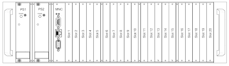
On the front side of the enclosure, you find 20 slots, where up to 20 cards can be placed in.
Read chapters Config Parameters and Setup Parameters for instructions how to use this configuration and how to configure the redundancy.
It is possible to place a LFRX, LFTX or LFSW card in every slot. To install the desired card, put it into the slide rail until the front plate of the card contacts the mounting rail. The card has to slide in smoothly. If not, pull the card out and try again. Otherwise the connectors on the card edge or on the backplane might be damaged. After that fix the card with the provided screws to ensure a proper contacting of the connectors on the LFRX, LFTX or LFSW card with the connectors on the backplane.
Now you have to configure the system after placing a LFRX, LFTX or LFSW card. How to do this, is described in chapter Config Parameters .
To release a card, open the screws with which the card is fixed at the mounting rail. Now turn in the screw into the screw thread beside to push the card out of its socket. After that you can pull the card out of the unit.