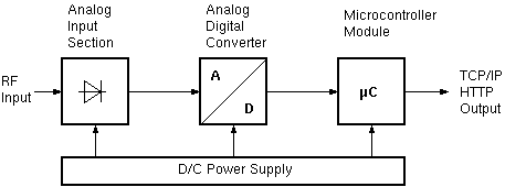
The sat-nms PowerSensor consists of the following four major parts:
In the analog input section a microwave detector provides a DC voltage which is depending on the input power range either proportional to the input power or proportional to the input voltage of the input power at the power sensor. The relationship between input power level and the DC voltage to be measured in the last instance by the analog to digital converter is not necessarily to be known exactly, as this is measured and calibrated during the in-factory calibration of each individual sensor.
The DC voltage coming from microwave power detector gets amplified in an operational amplifier. Via a switchable resistor network the gain of the amplifier is controlled by the micro controller, which allows a so called high and low sensitivity mode. The power sensor software will control this switch and either set the gain to a fixed high or low-sensitivity value or in 'auto' mode take full control about the sensitivity control and depending on the analog to digital converter (ADC) output value switch the sensitivity automatically.
At the output of the operational amplifier the DC voltage which is a measure of the RF input power is provided as input value to the analog to digital converter. The sat-nms PowerSensor uses a 16 bit ADC, this provides enough resolution to always guarantee the 0,01dB resolution in power level output via the web server.
The complete power sensor is operated by a 24V DC voltage source. This has the advantage that the already existing 24V supplies in a satellite ground station or an M&C System can be used to provide the supply voltage of the power sensor. The 24V supply voltage is routed via a EMV coupled inductor and a transsorber diode which switches off at voltages greater than 36V. This together with a SMD fuse protects the power sensor from to high input voltages or EMV disturbances introduced via the 24V supply line.
After this input and safety section a DC/DC converter provides the 5V DC voltage necessary for the microprocessor and digital part of the power sensor. Parallel to this a linear voltage regulator provides a so called analogue 5V which is independent from the microprocessors digital 5V supply and therefore more stable and less noise which is better for the analog to digital converter and its analog input section.
Beside the detector diode and the RF matching circuitry the RF sensor module contains a temperature sensor. The temperature registered by this sensor is used by software in the M&C module to perform the temperature compensation of the measured power.